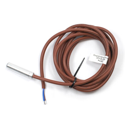
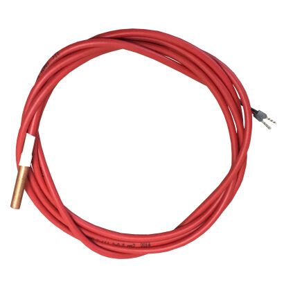
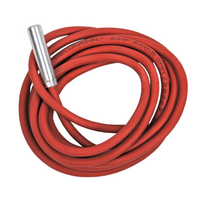
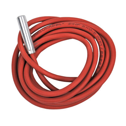

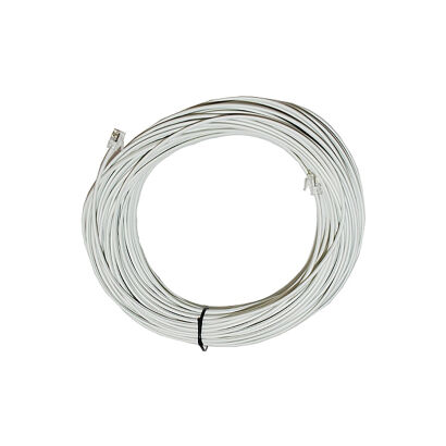
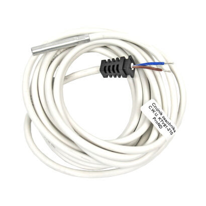
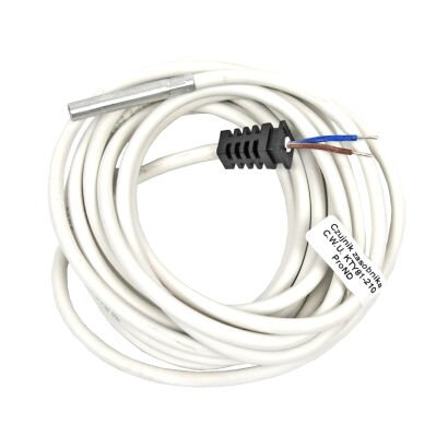
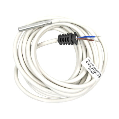
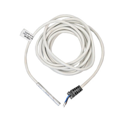
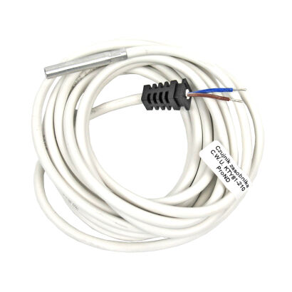
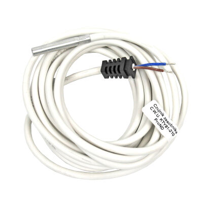
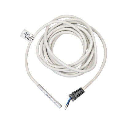
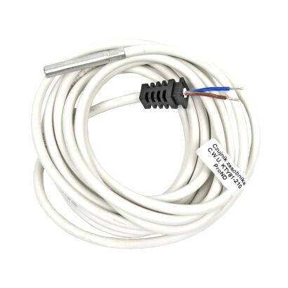
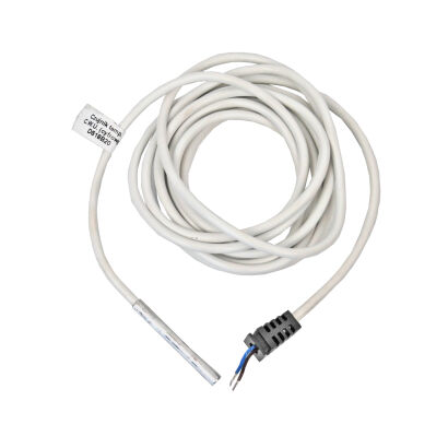
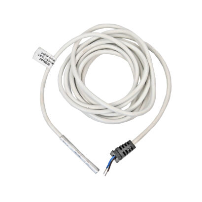
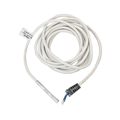
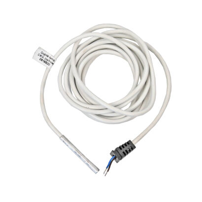
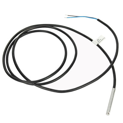
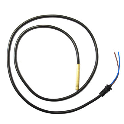
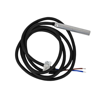
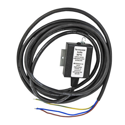
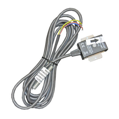
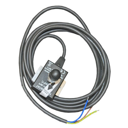
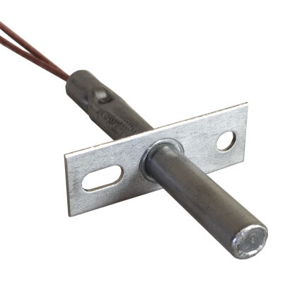
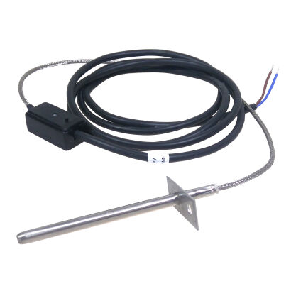
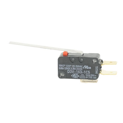
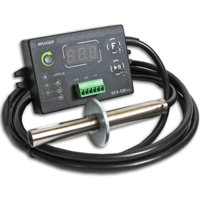
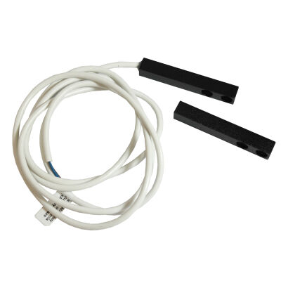
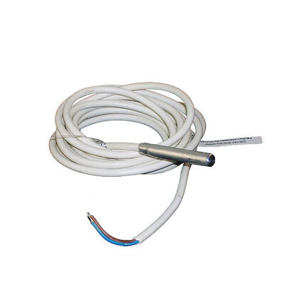
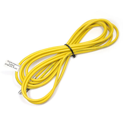
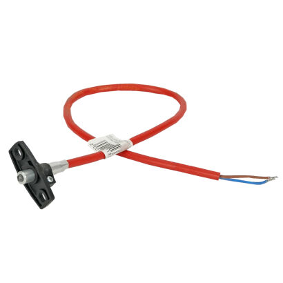
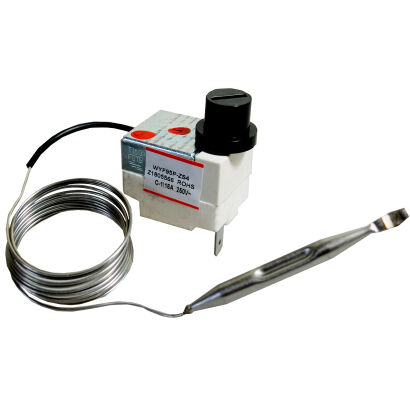
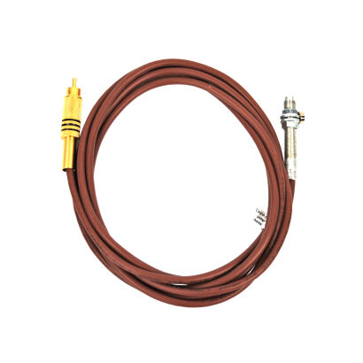
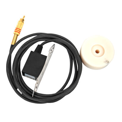
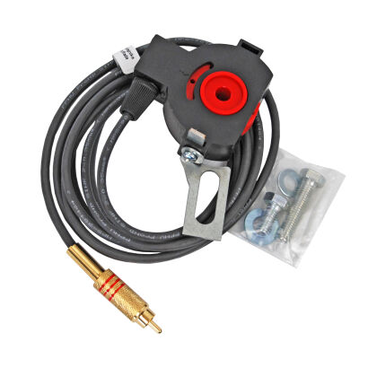
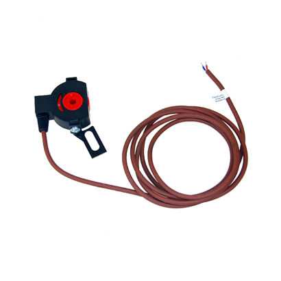
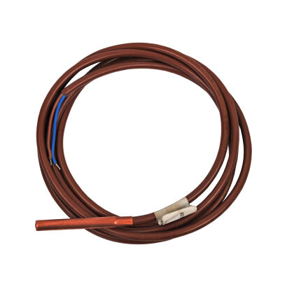
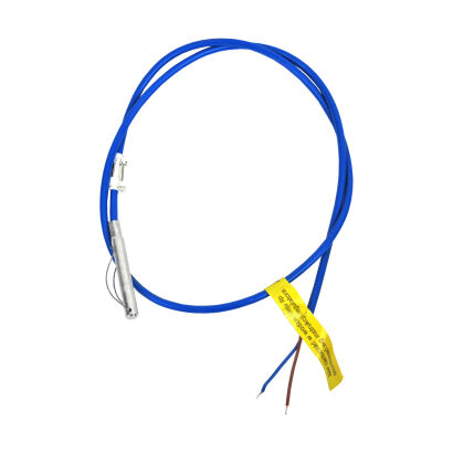
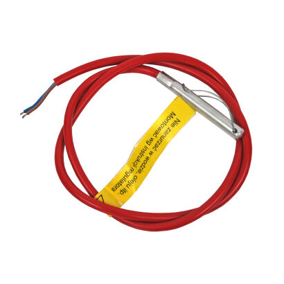
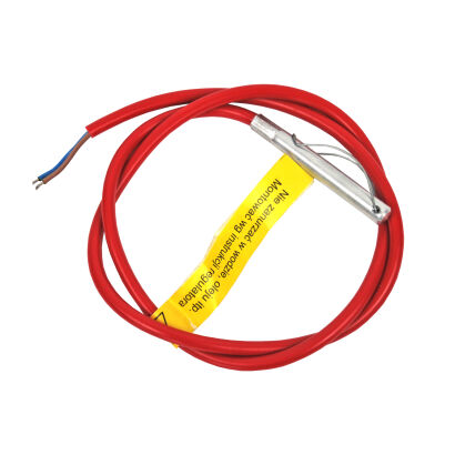
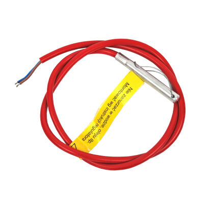
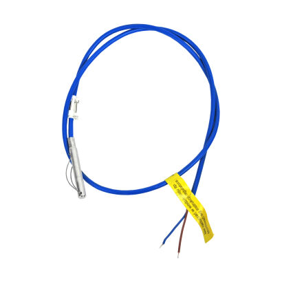
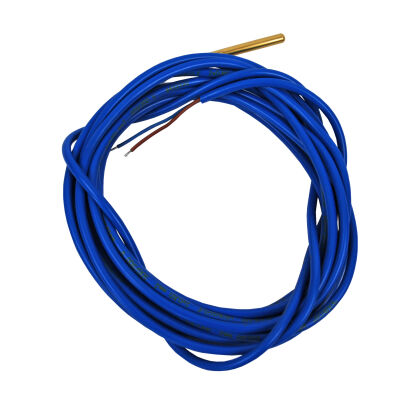
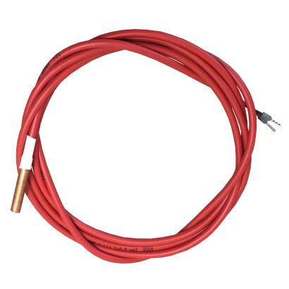
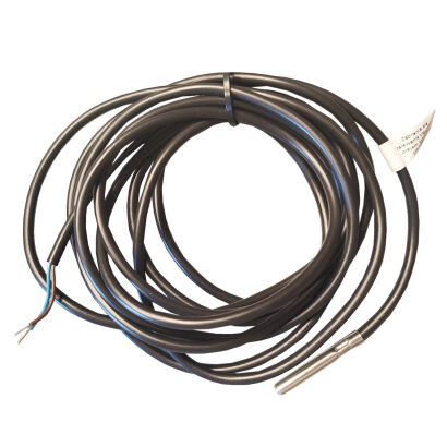
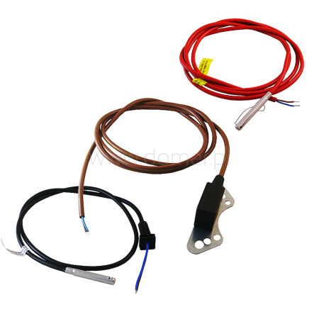
Selecting a sensor for the boiler controller starts with compatibility with the electronics, not just the cable itself. This category includes temperature sensors for the furnace and central heating system, i.e., CH, designed for specific controllers, as well as versions for measuring domestic hot water, i.e., DHW, flue gases, basket, tank, and mixer, and for operation under insulation. Different cable lengths allow replacing the element without modifying the existing installation.
A properly selected element transmits the actual temperature at the measurement point to the boiler controller. The controller then more stably controls the blower, feeder, and pumps, which improves the combustion process, reduces unnecessary downtime, and facilitates maintaining the set temperature.
Why does the furnace temperature sensor affect boiler operation?
The temperature sensor is the basis of boiler automation because the controller's decisions about fuel supply, air blast, and circuit activation depend on its readings. Incorrect measurement worsens the efficiency of the central heating system and may increase fuel consumption.
In practice, one system uses several control points:
- measuring the water temperature in the CH boiler
- measuring the domestic hot water temperature
- measuring the temperature of the feeder, basket, or tank
- measuring flue gas temperature or external temperature for weather control
The term pump activation temperature sensor usually does not mean a separate standard but refers to the function of measuring the boiler temperature. After exceeding the set threshold, the controller starts the CH or DHW circuit, and with feeder protection, it also reacts to a temperature rise that threatens ember backflow.
Selection according to the controller and installation location
Sensors for controllers are not universal. The same housing shape does not guarantee compatibility because the measurement type, electrical characteristics, and intended model of the controller matter.
When comparing versions, the following are important:
- signal type: analog KTY or digital DS18B20
- cable length from 1 to 4 m
- type of cable insulation, including silicone insulation, blue or red, and versions for insulation
- presence of STB protection, i.e., safety thermostat, or cooperation with an emergency thermostat
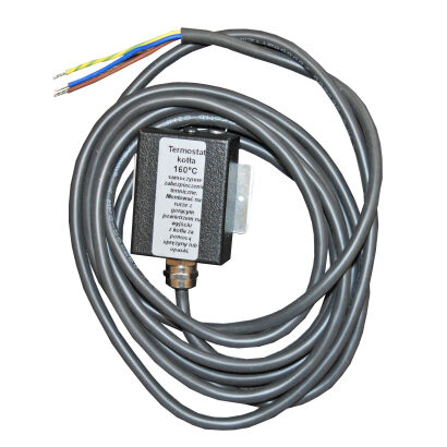
Besides measuring probes, there are also protective elements, including STB, emergency thermostats at 90 °C with reset, 160 °C variants for hot air, and basket thermostats in the range of 50-300 °C. For greater distances between the boiler and controller, the cable routing method is also important to avoid damaging the insulation on the housing edges.
The most common mistake is swapping a KTY sensor for a DS18B20 or vice versa. The reading may then be overestimated, underestimated, or not recognized by the controller at all.
How to recognize a damaged sensor in the furnace?
A damaged or incompatible sensor most often shows symptoms visible in the reading, not in the housing itself. The temperature reading may freeze at one value, jump by several degrees, or trigger a sensor alarm despite the boiler working correctly.
The effects are later visible in the automation operation. The pump turns on too early or too late, DHW heats unevenly, and the feeder and air blast operate inadequately to the actual temperature.
During verification, it is worth checking the cable continuity, connector condition, and cable routing. The flue gas temperature sensor and basket sensor operate under harsher conditions than the boiler probe, so insulation damage and cable overheating occur there more often.
Accuracy, measurement range, and durability in daily operation
The most accurate sensor does not have to be the most universal – it should primarily match the controller input and measurement location. For many boiler controllers, the typical measurement range of boiler and DHW sensors is 0-100 °C, while basket protections and elements for hot air operate at higher thresholds.
Accuracy in practice also depends on cable stability, proper probe mounting, and insulation resistance to temperature. Wired sensors remain the standard in boiler automation, so wireless variants do not replace probes if the controller manufacturer requires cable measurement.
When replacing, it is best to compare the sensor type, controller designation, installation location, and cable length with the old element and device documentation. Such selection facilitates installation and restores proper operation of the entire automation.
FAQ
What signals are used in sensors and what are the risks of swapping them?
The article describes two types of sensors: analog KTY and digital DS18B20. Swapping between them can lead to overestimated or underestimated readings or lack of recognition by the controller, which disrupts boiler operation.
What should be considered when choosing cable length and insulation?
You should select the appropriate length (1–4 m) and type of insulation (silicone, blue, red, or version for insulation). The cable routing method is also important to avoid damaging the insulation on housing edges.
What symptoms indicate a damaged sensor and what to check during verification?
Typical symptoms are frozen readings, temperature jumps, and false alarms. Check cable continuity, connector condition, and possible insulation damage, especially in flue gas and basket sensors that operate under harsh conditions.
 Polish
 Czech
 German
 Slovak
 Ukrainian